Flood Drainage Pumps: Types, Flow and Head
Compare pump types and rated duties, then match the pump, hoses and power supply to the site.
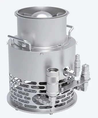
Rated duty examples
Each row describes a separate equipment configuration from technical literature. Figures are rated duty points, subject to the selected curve, controls and operating conditions.
| Configuration | Flow (m³/h) | Head (m) | Motor power (kW) |
|---|---|---|---|
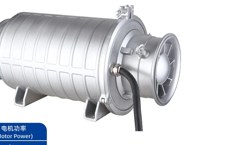
| Large-flow drainage | 600 | 8 | 22 |
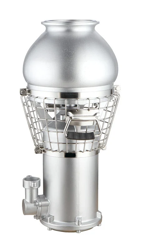
| High-head drainage | 200 | 50 | 45 |
| Surface self-priming | 300 | 20 | 30 |
Surface self-priming pumps
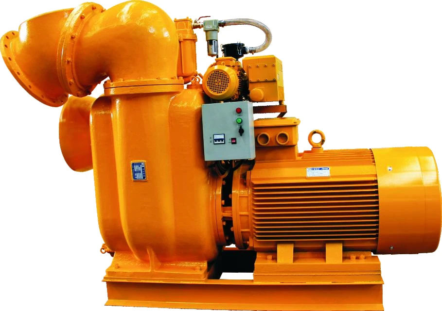
The pump stays on the vehicle, skid or ground and draws water through a suction hose. A vacuum-assisted priming system evacuates air from the suction line; a double-suction impeller admits water from both sides. These describe different functions. Check vertical suction lift, airtight suction hose, strainer, line length and available suction conditions. The pump head is the delivery duty, not the allowable suction lift.
Portable submersible pumps
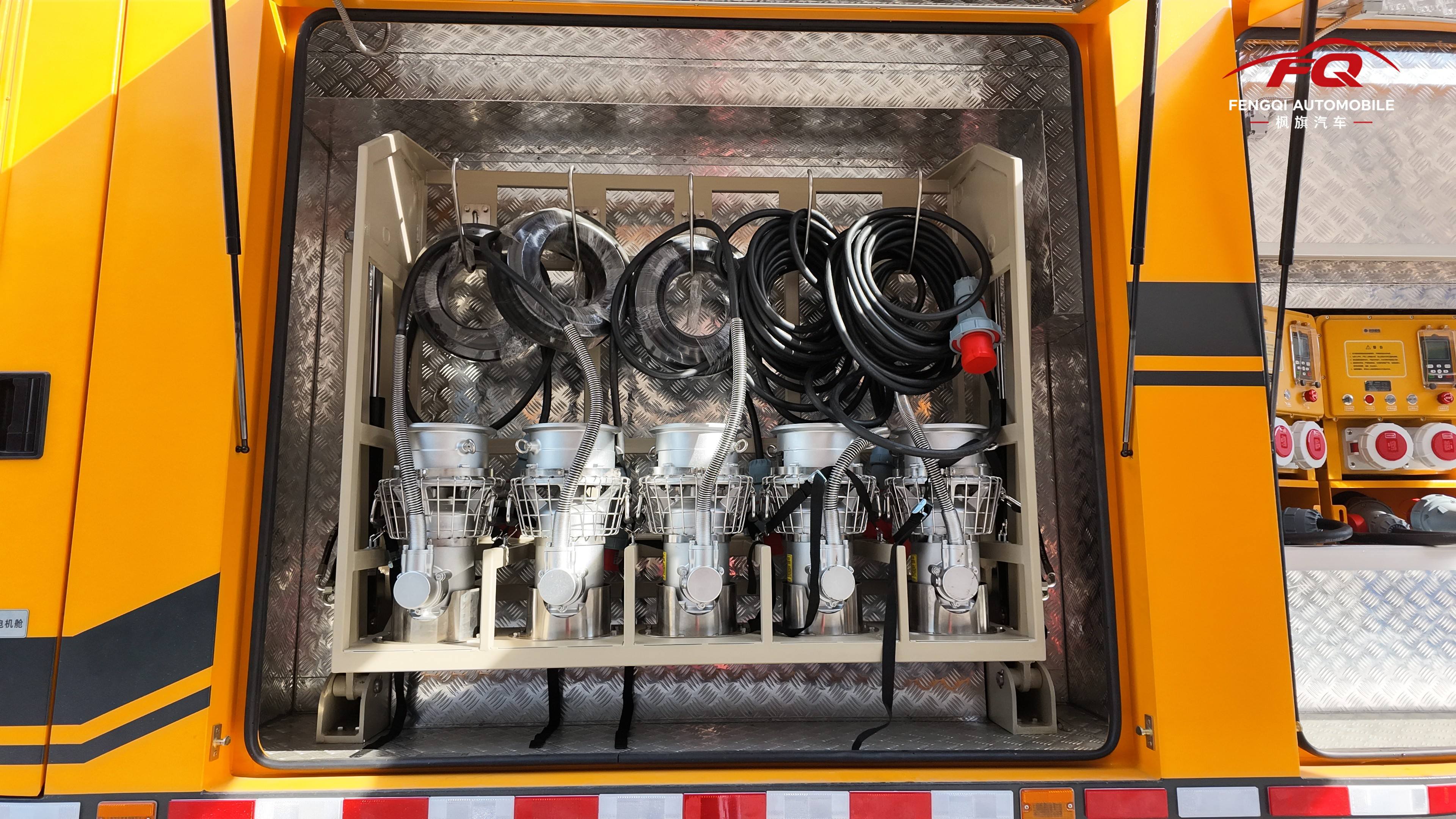
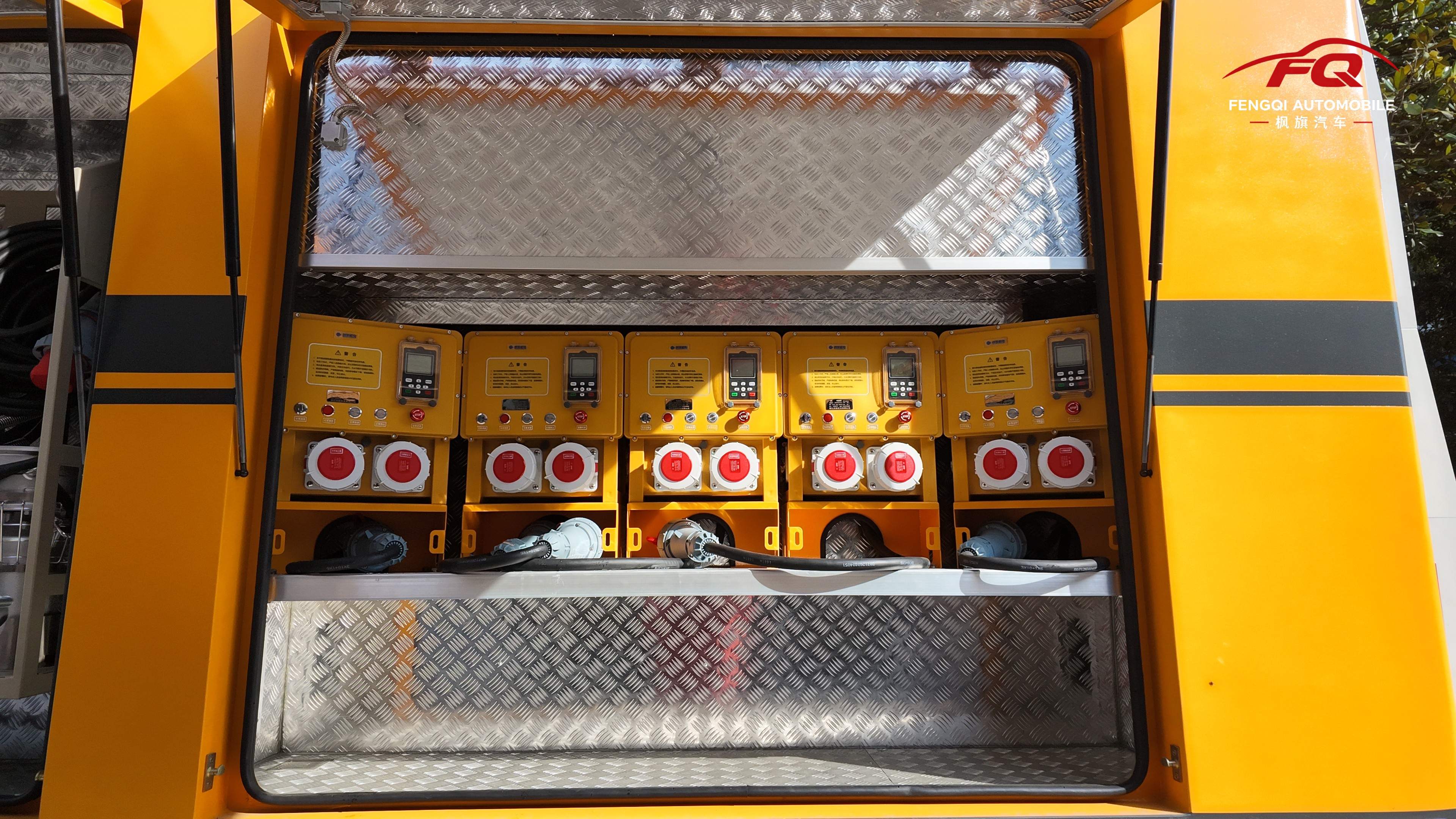
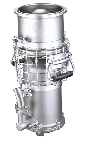
The pump is lowered into the water, reducing the need for a long suction line. Lightweight permanent-magnet versions use a matched variable-frequency controller; motor nameplate power alone is insufficient to select the generator. Check controller input, cable length, connectors, protection and cooling conditions. Floating and submerged deployment require different handling arrangements. Lift at the designated lifting points.
Large-flow drainage and high-head pumping
Large-flow axial-flow designs are suited to moving substantial volumes at relatively low heads. High-head configurations address elevation and pressure losses in longer hose routes. A bottom inlet can help remove shallower residual water, subject to the selected minimum water level. A booster pump adds pressure along an engineered discharge route; it must be matched to hose pressure ratings and the complete system duty.
Sewage and sludge duties
Submersible describes installation; sewage and sludge describe the fluid. Establish solids size, fibres, sand content, viscosity and concentration before choosing impeller and materials. A cutting mechanism addresses specified fibrous material and does not make the pump suitable for every slurry. Abrasive, dense or corrosive liquid may require a different pump.
Read flow and head together
Flow is stated in m³/h or L/s; head is stated in metres. For example, published equipment tables include separate rated duties of 600 m³/h at 8 m with a 22 kW motor, and 200 m³/h at 50 m with a 45 kW motor. These illustrate different configurations, not one adjustable specification or a vehicle performance promise. Read the actual curve and operating limits. Removing 600 m³ in two hours requires an average 300 m³/h before adding continuing inflow.
Vehicle power and deployment
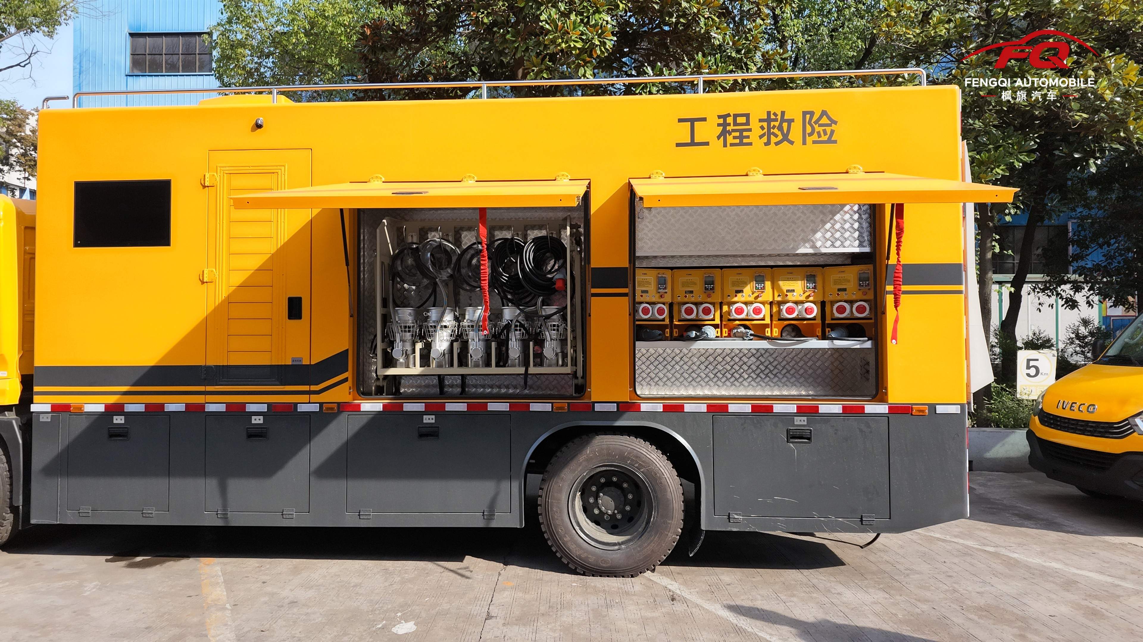
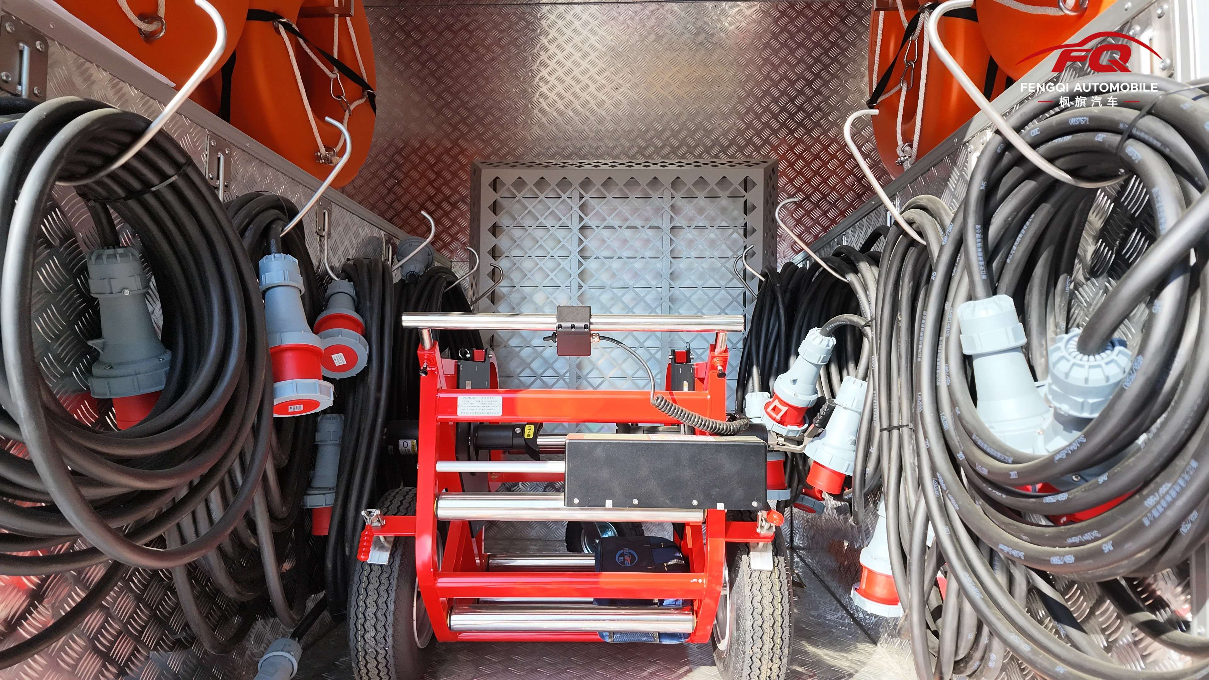
Calculate total head from elevation, hose friction, bends and discharge conditions. Match electric pumps to the generator and controller, or hydraulic pumps to required oil flow, pressure and cooling. Include hose reels, cables, pump mass, crane deployment, wet-equipment storage and maintenance access in the vehicle layout. Send water type, target flow, lift, hose route, operating time and site access for an initial review.
Pump vehicle layout